CSCE691
Traditional XR is clunky, when it comes to touch and manipulation. Would users be more adept at interacting in a virtual 3D space if we provided an XR experience that combined fine-grained tactile feedback with visual perception?
There's an existing gap between purely digital and physical prototyping processes. A seamless integration between these two realms can make the design process more intuitive and grounded in real-world interactions.
In essence, we will showcase a novel way to prototype, combining digital capabilities with physical inspiration. Our method has potential advantages in design fields where physical objects can guide or inspire the digital design process.
Meetings
Week 5: October 26, 2023 (Thu)
Week 5: October 24, 2023 (Tue)
Notes
Tada!
Here is the video of the working demo. This video showcases the following features:
- Snapping feedback
- Spring feedback
- Sequential/Cumulative free-form deformation
- History stack
- Heads-up-display (HUD) style history navigation interface.
Everything Became Simpler
Before, we had to imagine everything in our heads. When discussing with colleagues, we often found ourselves without a way to express our ideas, resorting to hand gestures, body language, and drawings. But now, having created it, the once abstract ideas have become concrete, significantly reducing the mental load for the upcoming challenges.
Now, It's Time to Read
Why certain experiments should be conducted, what hypotheses to set, and how to verify them. To determine the impact of our model on user performance using quantitative assessment tools, we need to read the previous papers. Only then can we set our goals.
Ideas
- Completing the task of drawing curves on the model surface will wrap up the essential feature implementation.
- Need to order parts necessary for the setup to be used in the experiment.
Week 4: October 19, 2023 (Thu)

No meeting took place
Notes
First Things to Do!!!
- Spring Feedback
- Giving force in the opposite direction when dragged with the mouse.
- Snapping Feedback
- Once when attaching.
- Once when detaching.
- Resampling.
- Spring Feedback
Then, What to Do Next
- Undo/Reset.
- Various UX considerations.
Effects (Haptic Material) Vary by Type
- Friction
- Static Friction
- Dynamic Friction
- Friction tends to move towards the center of the object if a bit of static friction is applied. Either static or dynamic friction can't be zero.
- Contact Force. This has a normal and reverse direction. In the normal direction, it feels like a buffer zone is created, giving a sense of primary and secondary contact. In reverse, it behaves like snapping/magnet effect, sticking to the secondary contact point when nearing the primary contact range.
- Spring Force. This also sticks when getting closer.
Interesting Ideas!
- Would providing a view from the pen tip in the corner of the screen make it easier to navigate in 3D space?
Ideas
Turns out it's quite fun and progress is being made.
Dragging and Dropping
- Acquire control point handle currently attached, and when button 1 is pressed, apply material to the current handle's control point like a tight spring.
- Hide the mesh renderer of the collider attached to the current stylus tip when it snaps.
- Who should check which control point is currently engaged? The agent? The control point?
- In drawing mode/transformation mode, having a different Z position for the haptic collider helps.
Resampling
- For line handling, this would be good to use: https://docs.unity3d.com/ScriptReference/LineUtility.Simplify.html
Making Dragged Control Points Accumulate
- The control point that the interpolator always needs to refer to (visible transparently in the game view, not directly manipulable) -> effectiveControlPoint.
- The control point engaged by the stylus, with haptic material attached (the interpolator should be affected when interacting with this, and should return to its original position after dragging) -> hapticControlPoint.
- The reference control point always in place, used to calculate spring force -> fixedControlPoint.
- A temporary point used only during dragging? Sum of the effective + haptic positions during this time -> intermediateControlPoint.
- During dragging, make the interpolator use the sum of effective + haptic positions, and update the effective at the end of the drag?
- At the start of the drag, temporarily get the coordinates of the paired effective control point. This is needed to add to the displacement.
History Stack/Reset
Ensuring that curves drawn by the user remain on the surface of the model that has undergone free-form deformation through control point manipulation.
Week 4: October 17, 2023 (Tue)
Notes
- Let's Stick with Unity
Everyone has a plan until they get punched in the mouth. I had a grand plan to use JavaScript + WebGL for the frontend and a Unity app serving as the server to communicate with a haptic device. Specifically, the plan was to open a websocket server in the Unity app that communicates with the haptic device and expose the interface of the haptic device to the JavaScript frontend through socket communication.
I simply tried to implement the function to retrieve the stylus position of the haptic device. It works perfectly fine. My electronjs app, which is a websocket client, connects to the Unity executable, which is a websocket server, and receives the stylus's position to move a cube in real-time within an HTML5 canvas.
Manual binding was necessary for serialized data transmission/reception. The numerous types of events sent by the haptic device. I realized that I had to manually connect each one to mediate communication between the electronjs and the Unity app. Would it have been better to use WebIDL? I saw myself getting sidetracked and wasting time on irrelevant things. Quick surrender is a strategy.
Don't blame the tools. To be honest, I was ignoring the fact that you can really create beautiful and lovely interfaces with Unity. (It just takes more time) It's my project, my baby. Don't hold back love until the deadline.
- A Long Way to Go
Just to list a few, there are many features to implement like history function, spline resampling, context menu, etc. I also need to read past papers related to this research. Write a proposal for a pilot study experiment. And write a storyboard.
More than anything, I can easily guess that a lot of time will be spent catching bugs that will emerge. I have to quickly make progress while simultaneously implementing features and bug tracking. It's not like there's a separate QA team. I have to create and fix it myself.
Week 3: October 12, 2023 (Thu)
Notes
What experience/function will we deliver?
- Storyboard-ing our idea would help us figuring them out (like cartoons)
- How do you want to represent user actions intuitively in the storyboard? Representing them through clicks or taps can be a way
Let's complete a pipeline
- We now have the parts. (free-form deformation, drawing on the surface) Now it's time to assemble them to create a program
Do we post-process the sampled points?
- They are currently stored as
std::vector<std::vector<Vector3>> - Smoothing (Laplacian smoothing, Exponential smoothing)
- Resampling (Equidistant resampling[1], many more...)
- They are currently stored as
Let's start with a simple force feedback
- We can do more advanced feedback later (like vertex/edge/face mode, etc.)
Bare necessities
- Things like undo/redo/reset
- undo/redo would require good state management
- A way to provide a context menu (Because user cannnot use any other HIDs like a keyboard)
- If you right-click where you hold the pen, a context menu pops up in that location. (Like Apple VR, which is a fun idea)
- Should we allow users to select and erase drawn curves?
Ideas
There seems to be a need for rapid prototyping and iterative development on the frontend
I have a hunch that the unity engine won't cut it. One repl cycle, the unity environment is too slow. We need to move to a faster repl environment. A scripting language (Lua or Luau) or a combination (Go + ImGui) would be a good idea. I'd like to hide the haptic device interface as a service and develop the rest in an environment that allows for rapid prototyping.
How can we quantify abstract user experience reports?
PI says there's a hint in the journal version of his recent paper. I checked and there's something called NASA Task Load Index[2]. Looks interesting, because it's NASA.
Jotting down ideas for storyboarding!
I have to make it less like a bland collection of First World problems.
References
Week 3: October 10, 2023 (Tue)

No meeting took place
Ideas
It's time to graduate from the squeaky caffeine bottle. How should I set up the lab? I'd like it to be simple yet robust
Unwavering comfort, on a heavy metallic base. Install a thin and long pedestal-like object in the center of the base plate. It would be great if it could be tightened with something like a clamp, but at the same time, there's a directional slot so that just by inserting it, you can easily estimate the orientation of the installed model.
I praise the simplicity of the FDM family, but I don't have time:
Wait for three hours and change the fill rate and try printing again. Try slicing again. Adjust the hang. Set up the support differently. Pre-heat the printing bed this time. Build the gcode again. This can be somtimes cumbersome.
Fast and reliable precision that money can buy
The lab setting I imagine: https://www.baselabtools.com/Solid-Aluminum_c_12.html.
Week 2: October 5, 2023 (Thu)

No meeting took place
Notes
- The reason the model had a problem last time was simply because I miscalculated the cost in the objective function. I used the wrong norm.
cost = sum(norm(V_pred - V_target));     % ftw cost
cost = sum(sum((V_pred - V_target).^2)); % proper cost- I corrected the problematic objective function. As PI suggested, I'll break down the problem and test it.

In the image above, the green slab represents a virtual object in the game engine, while the pink slab represents a physical slab in the real world (obtained by sampling the top four corners through a haptic stylus). If I didn't make any mistakes and the work is going smoothly, the green slab should arrive where the pink slab is, through the transformation matrix obtained from our modeled objective function.
Shall we first look at just the translation?minseopark:

minseopark: It works!!!
Shall we also try the rotation?minseopark: It's perfect
How does it fit so perfectly? It looks flawless no matter how you look at it.
WARNING
It seems to contain non-uniform scaling transformation (since the length of the edges is not preserved during iterations, it doesn't seem to be a rigid transformation), but we can find the data we need right now! We'll re-visit this in the near future.
- What if we provide an arbitrary transformation as a target?minseopark: our model never gives up
 (proud of it)
Ideas
Optimization is awesome!
It seems that creating something that wriggles and appears alive, or topics of similar interest, are often linked to optimization, which is truly fascinating. The current situation is unique; Optimization is being discussed in animation classes, geometric modeling classes, and even in MIT 18.06. From my two-month observation since coming here for my studies, I have a hunch that if one masters optimization, they wouldn't have to worry about making a living.
References
Week 2: October 3, 2023 (Tue)
We successfully discovered the hidden 35mm. The rod painted in green represents the virtual extension from the gimbal to the pen tip.
Watch video (Without Correction)
Watch video (With Correction)
The precision of the haptic device with error correction was truly remarkable. However, the filter fed to the solver seems a bit excessive; there appears to be lagging between the pen's movement and sensor reading.
Watch video (Drawing on the surfaces)
We were able to implement a basic free-form deformation.
Watch video (Trilinear interpolation)
Talks
I couldn't get the transformation matrix right. What did I do wrong?
Let's go step by step, simplifying the problem as much as possible. Start with just the translation, then the rotation. If that works, then combine translation and rotation. The scaling factor might play a role, so let's try not to filter the resulting rotation matrix with svd.
Notes
I implemented a simple free-from deformation. I'm considering the feedback to provide through the haptic device when users manipulate the control points. How and how much force should be provided?
There would be two types of forces to provide through haptic feedback. One would be a snapping force, like a magnet sticking when the haptic stylus approaches the virtual control point. The other would be a spring force when pulling the virtual control point through the stylus. Implementing both forces doesn't seem too difficult; they should feel just like snapping and springing. However, further consideration is needed to determine which provides a better user experience. It might be beneficial to consult experts with experience in user experience research on this matter.
Ideas
References for implementing free-form deformation
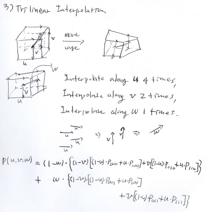 Most hints were obtained from animation class notes. [1] It was merely an extension of Lab 5. [2] Online resources were also very helpful. It remains to be seen whether trilinear is sufficient as the project progresses.
References
- Lab 5 - Bilinear Interpolation
- Free-form Deformations of Solid Geometric Models (Explained)
- Free-form Deformations of Solid Geometric Models
Week 1: September 28, 2023 (Thu)
After last week's meeting, I showed up with a calibration model using four vertices.
Talks
We were able to create a calibration model. However, to achieve the expected precision, we believe that the reference model should also be precise. I propose this lab setup. What do you think??
Precision is a nice addition, but it can also be de-prioritized a bit. Let me give you an example. Watch my hand here (moving the mouse device left and right). And look at the monitor here (the mouse pointer on the screen also moves left and right). How do we know how to move our hand to move the mouse pointer on the screen left and right?
We humans are able to perform this translation quite naturally, unintentionally, and effortlessly. To the extent that we don't overcome this perception, we can compromise on the calibration error, or in other words, we can compromise on the error if the on-screen haptics pen (rendered along the MVP matrix) gives enough of a perception that it is moving along the actual haptics pen.
There seems to be a drift when I hold the stylus horizontally. Can I trust the reading from the device?
This is because the position provided by the device is the center of the gimbal, not the tip of the stylus pen. We had the same problem. Try measuring the length from the center of the gimbal to the tip of the pen with a ruler. That's how far you should go from the center of the gimbal, along the axis of the stylus, to calculate the actual position of the stylus tip.
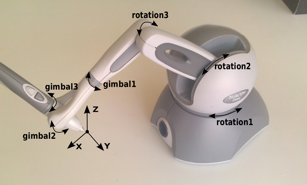 Image reference from [1].
Notes
Find the actual position of the stylus. Try to calculate the actual position of the nib in the game engine using the numbers we found empirically in a previous project (gimbal center to the nib of the stylus is around 35-40 mm). We've been there, done that, and found the answer the hard way. We even had direct access to the device's motor encoder to get the raw data.
Find the right camera transform. When the user shakes the device from left to right, the device on the screen should also shake from left to right. Just like the mouse in the previous example. We need to find a mapping between the position of the physical device and the on-screen device. One that makes the user feel like the haptic device is their limb.
These are just the preliminary steps before we move on to the actual design process. Lots of fun stuff awaits in the next step. For now, let's keep things light, taking only the essentials.
References
Week 1: September 26, 2023 (Tue)
Tried to implement the calibration steps, but it didn't work. Not accurate enough and seems to have some instrument error.
Watch video
Talks
I want to find a transform matrix, that allows me to register an object located in real space to a virtual space (in a game engine). Right now I use the positions of the four vertices, but I'm not satisfied. Is there a better way?
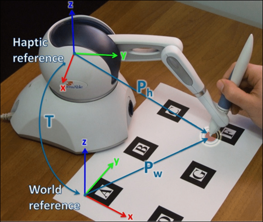 Image reference from [1].
If 1) the origin of the device in the virtual space is known, and 2) the dimension of the reference model in the real space is known, the mapping between the two spaces can be obtained using the four vertex data registered by the haptic device.
Let
be the four vertices of the reference model in the virtual space before calibration, and let be the four vertices of the reference model in the real space sampled by the haptic device. ( ) Consider a 4x4 transform matrix that sends an object from one space to the other. We can represent this matrix as a combination of a 3x3 rotation matrix and a translation vector of size 3. Now let's add 9, the number of all components of , and 3, the number of all components of , for a total of 12 unknowns. We can perform the optimization, as shown in
, in space, with the distance between and as cost function. In other words, and , we can find a rotation matrix and translation vector that minimize the distance between and . We can first check if our model works by using
fminuncprovided by Matlab. If it works, it seems possible to convert it into a script that can be used in a game engine.TIP
Remember that we need to obtain a valid rotation matrix via SVD. There is no guarantee that
obtained by this optimization is in . matlab[u s v] = svd(R) rot = u * v'
Ideas
- Maybe I can write a C# wrapper for the Ceres solver?
- I'll have to talk to PI about setting up a mini lab for a precise calibration setup. I think it would be better to have a steel frame and panels to make it perfect.
References
Week 0: September 21, 2023 (Thu)
This time, we prepared a demo that continuously samples points while sliding on the surface.
Watch video
Talks
Why do we need this study?
Our research aims to revolutionize the way prototyping is approached by blending physical and digital realms, thereby making the design process more intuitive, creative, and effective.
What would be the method?
The results produced by the collaboration of a person's delicate sense of touch and spatial awareness through vision can sometimes be remarkable. One of the spaces where such synergy can be maximized is the virtual space. However, our ability is limited by the blunt interface.
Have you ever played a game with a VR device? Recall the traditional VR environment. Do you remember the large and clunky buttons? We aim to create new possibilities in the interaction between people and space by combining previously absent detailed tactile information with cognitive abilities.
How can we know if our new model truly improves the user experience?
We will design an experiment where the participants can sufficiently experience our model. After that, we can validate it through an unstructured interview. We will evaluate the opinions of the participants who experienced our model from various perspectives. (e.g. [1]§ 4.1)
Notes
We plan to conduct follow-up experiments for the aforementioned paper[1] using the following items:
- Appropriately matching the spatial coordinates between the real world and the screen world.
- Drawing curves on surfaces. The same action should occur on the screen. When drawing a curve on the surface of an object in real space using a stylus pen, the same curve should appear in the virtual space.
- Providing force feedback along with free-form deformation. As shown in [1]§ Fig 2, if a control point is pulled, the virtual object on the screen would stretch accordingly, but the actual object would not move. To address this, we will set control points fixed around the actual object.
- Next, we will design the experiment.
- Then, we will conduct a user participation experiment, survey, and evaluate the results.
Previously, we used an optical tracking setup, but this time we are considering other methods. It would be a great bonus if we can track the rotation of an object using an IMU
Ideas
- Would drawing a curve on the surface look something like the following?
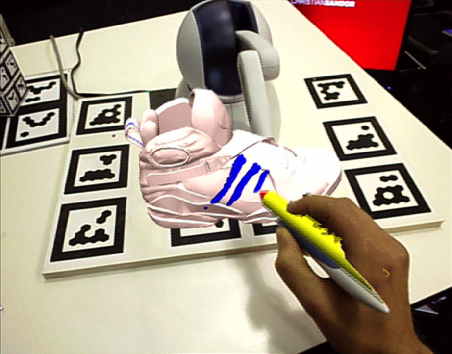 Image reference form [2].
 - Will the deformation be implemented in a way similar to the following? When adjusting the control points, how should we calculate the feedback force to provide to the haptic device? Can we use position based dynamics for this?
 Image reference from [3].
References
- QuickProbe: Quick Physical Prototyping-in-Context Using Physical Scaffolds in Digital Environments
- HARP: A Framework for Visuo-Haptic Augmented Reality
- Wrap Effector
Week 0: September 19, 2023 (Tue)
I prepared a demo about curve sampling that was discussed in last week's meeting. I also tried implementing the features mentioned in [1]§ 2.5 (auto loop generation, end points snapping).
Watch video
Notes
There will be:
- Curve fitting
- Cage manipulation
- User survey
It seems like I will be working more as an active research body rather than just a simple coder.
There should be a code related to curve resampling developed in previous research.
Implementing cage or free-form deformation should be straightforward. The lab material from the animation class (Lab 5 - Bilinear Interpolation) should help.